 1987
1987
 2019-03-20

The Verge today published photographs of a prototype logic board that Apple’s engineers used to create the original iPhone back in 2007. While the company would later move on to much smaller test boards for subsequent iPhone models, these never-before-seen images definitely offer an interesting, unique look back at the development of the iconic handset.
It being a prototype means it was much bigger than the shipping logic board in the original iPhone. Despite the ugly mess that it is, the prototype board could be connected to a modern computer and iTunes would see it as a regular iPhone needing restoring.
"Our source explains that you can also attach this to iTunes, via the 30-pin connector on the side of the board, and it detects it as an iPhone ready to be restored."
The unit shown on the images is an engineering validation test (EVT) sample that was used by select iPhone engineers to test the early iPhone software and the wireless radio stack.

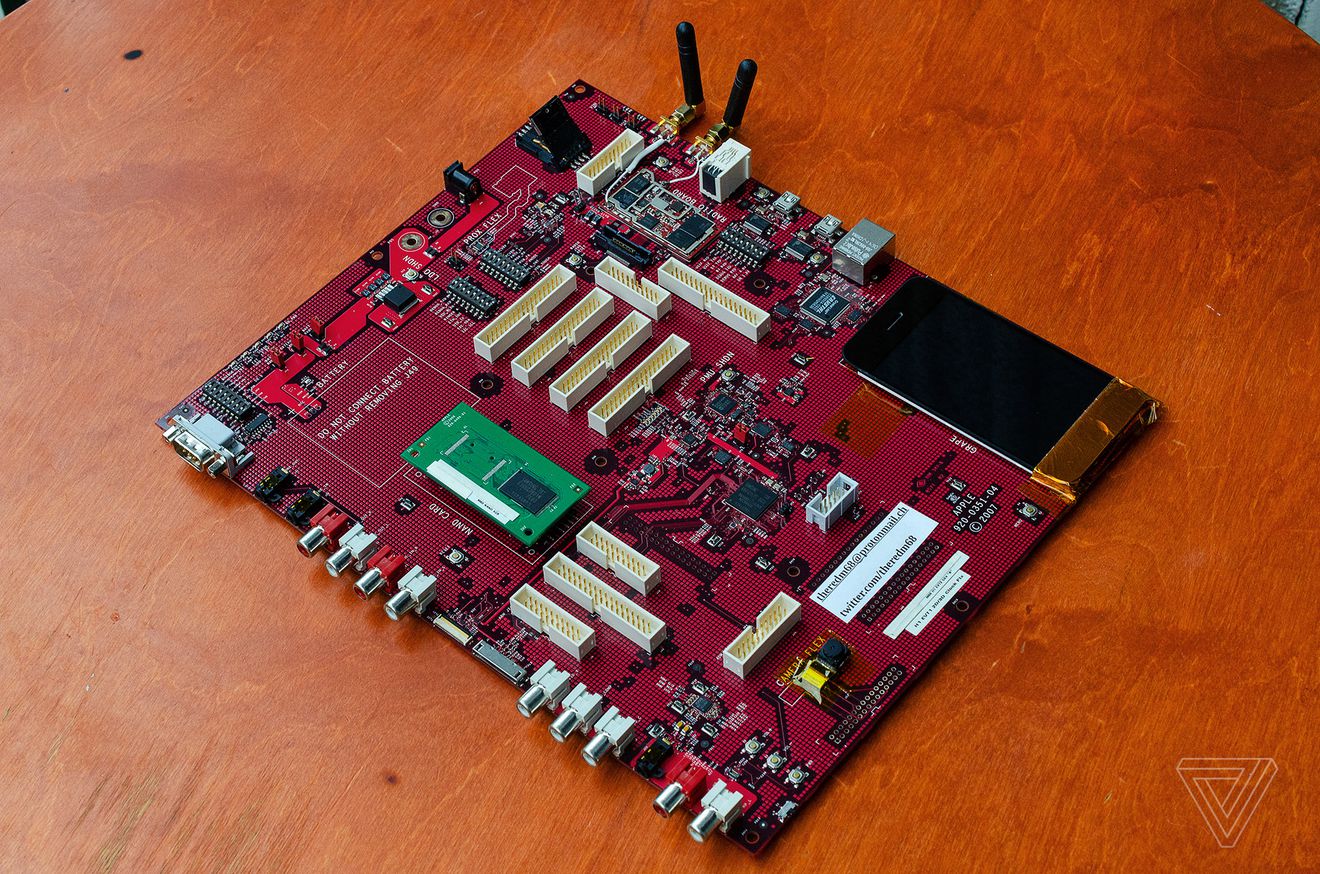
The PC-style development motherboard contained nearly all of the iPhone’s parts spread out across a large surface area. The unit shown on the photographs embedded in this article is the original iPhone M68 prototype board from 2006 and 2007.
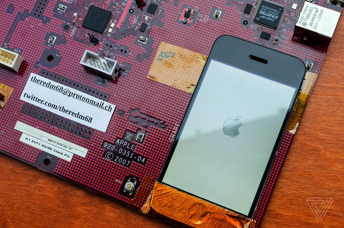
"On this particular development board, there’s even a screen, but the iPhone’s home button (known here as the menu button) is mounted on the board to the left of the display and the power and volume buttons are on the left-hand side of the board.
We got a chance to boot this prototype and it simply powers up to the Apple logo. Engineers using this particular board would have booted into something similar to a command prompt to test kernel changes."
There are some interesting connectors on this thing:
"Two mini USB connectors flank the side of the board, which were used by engineers to access the main iPhone application processor and radio (baseband). Apple engineers could use these mini USB ports to code for the device without ever seeing the screen."
And here’s your interactive look at the development board (drag the horizontal line).
But how would they test voice calls?
"To the right of the radio board, you’ll see an RJ11 port, which is the same registered jack that’s used by regular landline phones. Apple used this so that engineers could plug a regular landline phone headset into this iPhone development board and test voice calls.
Other ports were used in testing, too.
"Elsewhere on this board, you’ll see lots of white connectors with pins. The smaller ones are JTAG connectors used for low-level debugging. Engineers could connect signal probes to some of these connectors to monitor various signals and voltages, allowing developers to test key software changes to the iPhone and make sure they weren’t negatively impacting the hardware."
To keep the iPhone project secret from other employees, some version of the prototype board lacked an integrated screen and had to be connected to an external display.
"If an engineer inside Apple received a development board like this without a screen, component video and RCA connectors on the side of the board could be used to connect it to a display. Engineers could also test headphone connectivity, thanks to stereo line out ports on the side."
But how could they possibly test cameras and batteries with this board?
"Even the iPhone’s main camera is mounted on the board for testing and there’s a giant space left to test the battery. If engineers didn’t have a battery connected, a DC connector at the top can be used for external power. Apple also left room for what is marked as ‘prox flex’ for proximity sensor testing."
They could even test various peripherals with this thing!
There’s a serial connector at the top that was used to test iPod accessories since the iPhone also used Apple’s 30-pin connector and there’s even a LAN port for connectivity.
Another interesting observation: Apple only uses red printed circuit boards for prototype iPhone hardware. Production units typically incorporate circuit boards in blue, green and other colors.
Source: idb